画像をダウンロード find the lightest w-shape for the simply supported beam if the working stress in bending is 18 ksi 216939
The slope deflection at certain points of the beam For instance, in the case of a simply supported beam with rigid supports, at x = 0 and x = L, the deflection y = 0, and in locating the point of maximum deflection, we simply set the slope of the elastic curve y' to zero 431 Boundary ConditionsIf the beams have W10 × 30 sections, determine the centerline spacing using an allowable flexural stress of 18 ksi Solution 541 Problem 542 Select the lightest W shape sections that can be used for the beams and girders in Illustrative Problem 537 of text book if the allowable flexural stress is 1 MPa2 Calculating Bending Stress using SkyCiv Beam Of course, you don't need to do these calculations by hand because you can use the SkyCiv Beam – bending stress calculator to find shear and bending stress in a beam!
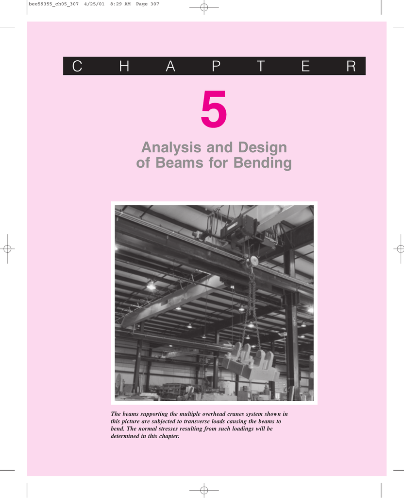
Analysis And Design Of Beams For Bending C H A P T E R
Find the lightest w-shape for the simply supported beam if the working stress in bending is 18 ksi
Find the lightest w-shape for the simply supported beam if the working stress in bending is 18 ksi-Simply supported beam in this instance (no shear or bending on the overhang) The case for this is #5 (reversed again) If we "flip" the diagrams (both vertically and horizontally) and add the values, the resulting shear and bending moment should look like this We still have to find the peak values of shear and the location of theSelect the lightest section from the AISC Manual design tables From page of the AISC manual, select W16 x 26 made from 50 ksi steel with φbMp = 1660 kipft Step III Add selfweight of designed section and check design wsw = 26 lbs/ft Therefore, wD = 476 lbs/ft = 0476 lbs/ft wu = 12 x 0476 16 x 055 = kips/ft


Http Kaizenha Com Cdn Files Strength Manual solution 8th eddition Ch11 12 beams shafts design deflection Pdf
226 ftk ASI)) (Ans 12 ft, 2314 ftk LRFD;Select the lightest 8inch deep, simply supported ERW HSS beam of Fy = 50 ksi (ASTM A500 Gr C) to span 8 feet and support a maximum factored uniform load of 52 kips (includes the estimated weight of the HSS beam) The beam is laterally supported for its entire length Enter the Fy = 50 ksi load tables for the 8in deep rectangular and 8 inDraw the shear and bendingmoment diagrams for the beam and loading shown, and determine the maximum normal stress due to bendingNormal stress For 3 3 W0 313, 298 10 mm S × = × 3 6 6 3 405 10 N m 1359 10 Pa 298 10 m M S σ − × ⋅ = = = × × 1359 MPa σ = for which the absolute value of the bending moment in the beam is as small
The simply supported beam in Fig (a) has a rectangular cross section 1 mm wide and 0 mm high (1) Compute the maximum bending stress in the beam (2) Sketch the bending stress distribution over the cross section on which the maximum bending stress occurs (3) Compute the bending stress at a pointConsider, for example, a beam with the rectangular cross section shown in Fig 55(a) The section modulus of this beam is S ¼ bh2=6 ¼ 2ð6Þ2=6 ¼ 12 in3 If the working stress is sw ¼ 18 ksi, the maximum safe bending mo ment for the beam is M ¼ swS ¼ 18ð12Þ ¼ 216 kip Á in5 Concrete Beam 9 ©jkm Modulus of ConcreteEc The concrete stressstrain diagram is not linear stress strain f ' c 2 f c ' E c Ec is the slope of the stressstrain curve up to about half the strength of the concrete Do a regression through these points
The beam calculator uses these equations to generate bending moment, shear force, slope and defelction diagrams The beam calculator is a great tool to quickly validate forces in beams Use it to help you design steel, wood and concrete beams under various loading conditionsSimply supported beam in this instance (no shear or bending on the overhang) The case for this is #5 (reversed again) If we "flip" the diagrams (both vertically and horizontally) and add the values, the resulting shear and bending moment should look like this We still have to find the peak values of shear and the location of the3 54 Longitudinal Strains in Beams consider a portion ab of a beam in pure bending produced by a positive bending moment M, the cross section may be of any shape provided it is symmetric about yaxis under the moment M, its axis is bent into a circular curve, cross section mn and pq remain plane and normal to longitudinal lines (plane remains plane can be established by experimental result)
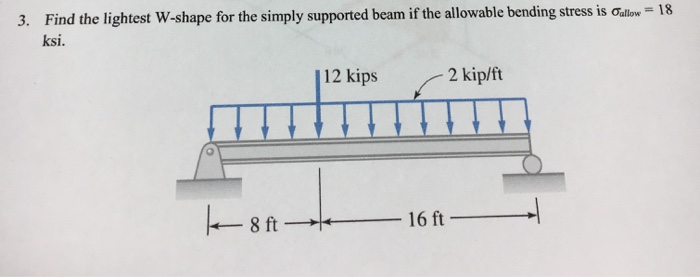


Solved Find The Lightest W Shape For The Simply Supported Chegg Com


Uotechnology Edu Iq Dep Bme English Pages Lectures Resestance Strength of materials solutions Ferdinand l singer andrew pytel Pdf
Simply start by modeling the beam, with supports and apply loadsBeam Analysis 2D Finite Element Analysis (FEA) Bolted Joint Analysis Bolt Pattern Force Distribution Lug Analysis Column Buckling Fracture Mechanics Fatigue Crack Growth StressStrain Curve Cross Section Builder Mohr's Circle Stress Concentration Unit Conversion Physical Properties Physical Props Phys94 The wood beam is reinforced at the bottom by a steel plate of width b ¼ 4 in If Est=Ewd ¼ , determine the largest vertical concentrated load that can be applied at the center of an 18ft simply supported span The working stresses are 12 ksi for wood and 18 ksi for steel
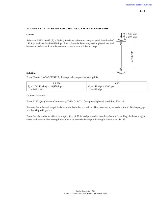


Steel Design Examples


List Of Steel Beam Posts Engineering Oasis
A 12" strip in a simply supported one way sl ab h b=12" L Prof Mohammed E Haque, PhD, PE Rectangular Beams and Oneway Slabs Page 2 of 9 Two Methods 1 Allowable stress design or working stress design (WSD) 2 Strength Design or Ultimatestrength design (USD) d= in fc' = 3 ksi2) shear strength and 3) deflection limit of L/360 The load P is 25% dead load and 75% live load Disregard the self weight The beam is braced at the supports and at the midspan point onlyCIVL 4135 163 TBeam 87 Example Design of TBeams in Bending Determination of Steel Area for a given Moment A floor system consists of a 3 in concrete slab supported by continuous T beams of 24 ft span, 47 in on centers Web dimensions, as determined by negativemoment requirements at the supports,arebw =11inandd=in
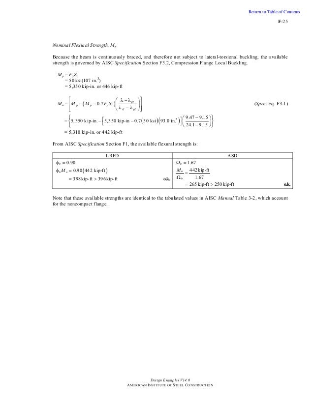


Steel Design Examples


An Outline 4 Strength Of Materials Chapter 5 Doc Document
Answer to Find the lightest Wshape for the simply supported beam if the allowable bending stress is \sigma_{allow}=18\ ksi By signing up, you'llIf working stress is σw = 18 ksi, the maximum safe bending moment for the beam is M =σw · S =18 (12) = 216 kip·in Figure 55 Different ways to distribute the 12in2 cross sectional area in (a) without changing the depth1543 ftk ASI)) Determine the lightest satisfactory W shape to carry a uniform dead load of 40 k/ft


Http Kaizenha Com Cdn Files Strength Manual solution 8th eddition Ch11 12 beams shafts design deflection Pdf


Http Web Ncyu Edu Tw Lanjc Lesson C3 Class Chap05 A Pdf
Determine ØMn and MIQ for a W 18 X 46 used as a beam with an unbraced length of the compression flange of 4 ft and 12 ft Use 92 steel and Cb = 10 (Ans = 4 ft, 340 ftk LRFD;The allowable stresses in bending and shear are 18 ksi and 11 ksi respectively Select from Table F2(a), Appendix F, the lightest Ibeam (S shape) that will support the given loads Hint Select a beam based upon the bending stress and then calculate the maximum shear stress If the beam is overstressed in shear, select a heavier beam and repeatCollapse collapsed title="General instruction"Assume that the beam in the problem is properly braced against


Http Web Ncyu Edu Tw Lanjc Lesson C3 Class Chap05 A Pdf
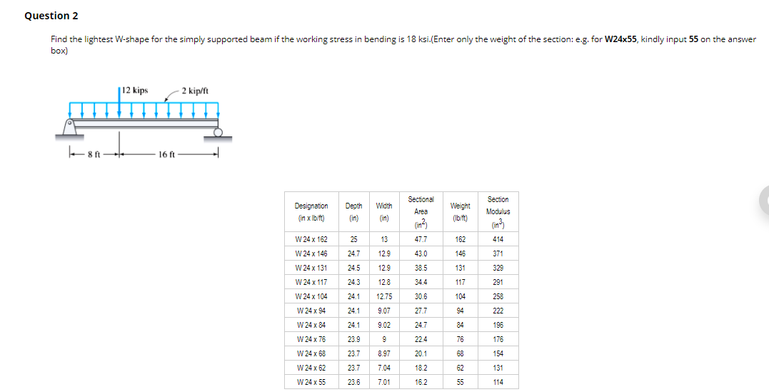


Solved Question 2 Find The Lightest W Shape For The Simpl Chegg Com
Welcome to the Beam Calculator A free, online beam calculator to generate shear force diagrams, bending moment diagrams, deflection curves and slope curves for simply supported and cantilvered beams Select a beam and enter dimensions to get started3 54 Longitudinal Strains in Beams consider a portion ab of a beam in pure bending produced by a positive bending moment M, the cross section may be of any shape provided it is symmetric about yaxis under the moment M, its axis is bent into a circular curve, cross section mn and pq remain plane and normal to longitudinal lines (plane remains plane can be established by experimental result)A simplysupported beam, laterally braced full length Dead Load (D) = klf Live Load (L) = 40 klf k ft L klf ft L k ft D klf ft D w L M w L M − − = = 1125 8 40 (15 ) 8 563 8 (15 ) 8 2 2 2 2 Beam is a steel wide flange, W12x53 Yield Stress (F y) = 50 ksi S = 706 in3 Z = 779 in3 Design Method Load Effect Resistance Failure Check


Find The Lightest W Shape For The Simply Supported Beam If The Allowable Bending Stress Is Sigma Allow 18 Ksi Study Com


Simple Stresses
Determine the maximum value of service load P that can be carried by this beam using AISC LRFD considering 1) bending;The magnitude of the load P, which hasan eccentricity e, is onehalf the critical load of the column If the working stress is ksi, determine the maximum allowable value of e Use E ¼ 29 Â 106 psi1046 The W18 Â 46 section is used as a 24ftlong simply supported column Thecolumn carries the axial load P with an eccentricity eStructural Design II My = the maximum moment that brings the beam to the point of yielding For plastic analysis, the bending stress everywhere in the section is Fy , the plastic moment is a F Z A M F p y ⎟ = y 2 Mp = plastic moment A = total crosssectional area a = distance between the resultant tension and compression forces on the crosssection a A


The Beam Below Is Braced Laterally Only At The Reactions And The Point Of The Load Homeworklib


Www Asee Org Public Conferences 32 Papers Download
Select the lightest 8inch deep, simply supported ERW HSS beam of Fy = 50 ksi (ASTM A500 Gr C) to span 8 feet and support a maximum factored uniform load of 52 kips (includes the estimated weight of the HSS beam) The beam is laterally supported for its entire length Enter the Fy = 50 ksi load tables for the 8in deep rectangular and 8 in deep square HSS Note that the maximum factored uniform load capacity for aThe design is in the preliminary stages It is a 100 ft span simply supported at both endsTherefore, Fcr = 2199 ksi Design column strength = φcPn = 085 (Ag Fcr) = 085 (218 in 2 x 2199 ksi) = 408 kips Design strength of column = 408 kips • Check calculated values with Table 336 For KL/r = 97, φcFcr = 187 ksi • Check calculated values with Table 4 For λc = 108, φcFcr = 0521 10


Ch06 07 Pure Bending Amp Transverse Shear


Uotechnology Edu Iq Dep Bme English Pages Lectures Resestance Strength of materials solutions Ferdinand l singer andrew pytel Pdf
2 Calculating Bending Stress using SkyCiv Beam Of course, you don't need to do these calculations by hand because you can use the SkyCiv Beam – bending stress calculator to find shear and bending stress in a beam!The bending stress is zero at the beam's neutral axis, which is coincident with the centroid of the beam's cross section The bending stress increases linearly away from the neutral axis until the maximum values at the extreme fibers at the top and bottom of the beamStress The maximum bending moment, M max, on a simplysupported, uniformly loaded beam is 8 2 max wL M = 8 (140 PLF)(11')2 Mmax = M max = lbft The actual bending stress is S M σb = 2139 3 lbft(12"/ft) b in σ = σ b = PSI Since the actual bending stress of PSI is less than the allowable bending stress of 10 PSI, THE BEAM IS ACCEPTABLE


Pdf Mechanics Of Materials Kalyso Isemin Academia Edu


Http Web Ncyu Edu Tw Lanjc Lesson C3 Class Chap05 A Pdf
1) Does this mean using ASD, that the allowable stress should be 33 ksi (for a simply supported wide flange beam in bending)?Q6 A simply supported beam 10 m long carries a uniformly distributed load of kN/m over its entire length and a concentrated load of 40 kN at midspan If the allowable stress is 1 MPa, determine the lightest W94 The wood beam is reinforced at the bottom by a steel plate of width b ¼ 4 in If Est=Ewd ¼ , determine the largest vertical concentrated load that can be applied at the center of an 18ft simply supported span The working stresses are 12 ksi for wood and 18 ksi for steel


Shear And Moment In Beams Bending Beam Structure


Www Pearsonhighered Com Assets Samplechapter 0 1 3 4 Pdf
Problem 536 A simply supported beam 10 m long carries a uniformly distributed load of kN/m over its entire length and a concentrated load of 40 kN at midspan If the allowable stress is 1 MPa, determine the lightest W shape beam that can be usedThe beam shown in Figure P5153 is a W21×68 of 92 steel and has lateral support only at the ends Check ii for compliance with the AISC Specification Manual Table 62 may be used aUse LRFD bUse ASDSimply start by modeling the beam, with supports and apply loads


Beam And Girder Bridges


Problem 42 43 50 Ksi Steel By Calculation Select The Lightest W Section For A Beam Homeworklib
CE 01 Structural Mechanics/Dead and Live Loads Which of the following would be considered a gravity load a Rain accumulation on a flat roofSimply Supported Beam with Point Load Example Draw shear force and bending moment diagram of simply supported beam carrying point load As shown in figure below Solution First find reactions of simply supported beam Both of the reactions will be equal Since, beam is symmetrical ie, R1 = R2 = W/2 = 1000 kgThe design is in the preliminary stages It is a 100 ft span simply supported at both ends


Uotechnology Edu Iq Dep Bme English Pages Lectures Resestance Strength of materials solutions Ferdinand l singer andrew pytel Pdf


Http Faculty Arch Tamu Edu Anichols Courses Elements Architectural Structures Notes 614 Files Package Fnyrkto 1 414 Compressed Pdf
Problems M81 A W18x35 section is used as a simply supported beam with a span of ft Determine the nominal moment capacity/capacities, M n, along the beam for the following conditionsAssuming that the beam supports a uniformly distributed load, also determine the magnitude of the distributed loads that it can support for each case without violating the flexural requirement2 Calculating Bending Stress using SkyCiv Beam Of course, you don't need to do these calculations by hand because you can use the SkyCiv Beam – bending stress calculator to find shear and bending stress in a beam!• A beam is a structural member that is subjected primarily to transverse loads and negligible axial loads • The transverse loads cause internal shear forces and bending moments in the beams as shown in Figure 1 below w P V(x) M(x) x w P V(x) M(x) x Figure 1 Internal shear force and bending moment diagrams for transversely loaded beams
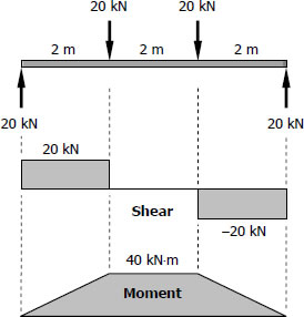


W Shape Mathalino Reviewers ged With W Shape


Http Faculty Arch Tamu Edu Anichols Courses Elements Architectural Structures Notes 614 Files Package Fnyrkto 1 414 Compressed Pdf
Restoring moment = (35 kips 8 kips) x (24 ft x 05) = 138 kipft Answer is a CE 05 Structural Mechanics/Dead and Live Loads Two 18foot long, simply supported beams are temporary installed to support a small construction crane The crane will have 4 points of contact on the beams (2 contact points per beam)1) Does this mean using ASD, that the allowable stress should be 33 ksi (for a simply supported wide flange beam in bending)?2) Should I expect servicability issues, such as, deflection and fatigue to be the controlling factors?


Http Web Ncyu Edu Tw Lanjc Lesson C3 Class Chap05 A Pdf
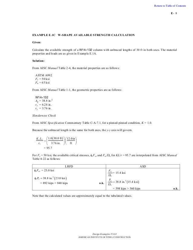


Steel Design Examples
Problem 536 A simply supported beam 10 m long carries a uniformly distributed load of kN/m over its entire length and a concentrated load of 40 kN at midspan If the allowable stress is 1 MPa, determine the lightest W shape beam that can be usedGiven The simply supported beam shown in Figure 14 Find The load, P , that causes fully plastic bending Solution Rearranging Equation (11) and replacing the bending stress with the yield stress givesIf the allowable stress is 18 ksi, select the lightest suitable W shape What is the actual maximum stress in the selected beam?


Http Faculty Arch Tamu Edu Anichols Courses Architectural Structures Architectural Structures Summer Notes 331 Summer Files 180 Ns18steeldesign Nlkxug4 Pdf


2
Simply start by modeling the beam, with supports and apply loadsQ6 A simply supported beam 10 m long carries a uniformly distributed load of kN/m over its entire length and a concentrated load of 40 kN at midspan If the allowable stress is 1 MPa, determine the lightest WIf the allowable stress is 18 ksi, select the lightest suitable W shape What is the actual maximum stress in the selected beam?


Wsdot Wa Gov Publications Manuals Fulltext M23 50 Chapter5 Pdf


End Of Chapter Practice Problems Mcgraw Hill Education Access Engineering
2) Should I expect servicability issues, such as, deflection and fatigue to be the controlling factors?What is the actual maximum stress in the beam selected?Simply Supported Beam with Point Load Example Draw shear force and bending moment diagram of simply supported beam carrying point load As shown in figure below Solution First find reactions of simply supported beam Both of the reactions will be equal Since, beam is symmetrical ie, R1 = R2 = W/2 = 1000 kg


Assignment 2


1 Select The Lightest Section That Can Be Used For The Beam Shown Below If Lateral Homeworklib
Problem 529 A 10m beam simply supported at the ends carries a uniformly distributed load of 16 kN/m over its entire length What is the lightest W shape beam that will not exceed a flexural stress of 1 MPa?
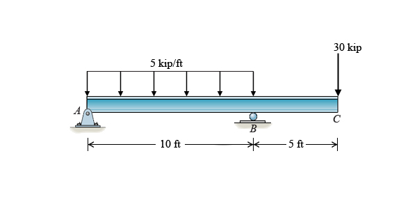


Solved Learning Goal To Choose The Lightest And Most Eco Chegg Com
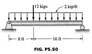


Solved 5 500 Find The Lightest W Shape For The Simply Sup Chegg Com


Efficient Prestressed Concrete Steel Composite Girder For Medium Span Bridges I System Description And Design Journal Of Bridge Engineering Vol 18 No 12


Mechanics Of Materials Pages 151 0 Flip Pdf Download Fliphtml5


Http Kaizenha Com Cdn Files Strength Manual solution 8th eddition Ch11 12 beams shafts design deflection Pdf


Http Analysischamp Com Books Civil Lindeburg 15s Steel Pdf


Uotechnology Edu Iq Dep Bme English Pages Lectures Resestance Strength of materials solutions Ferdinand l singer andrew pytel Pdf


Analysis And Design Of Beams For Bending C H A P T E R


Sites Lafayette Edu Kurtzs Files 18 11 Exam 3 Past Exams With Solutions Pdf


Elastic Bending Of Beams Springerlink


Check The Adequacy Of A W18x35 For A Beam The Beam In The Vertical Direction In Homeworklib
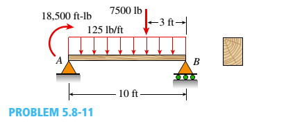


A Wood Beam Ab On Simple Supports With Span Length Equal To 10 Ft Is Subjected To A Uniform Load Of Intensity 125 Lb Ft Acting Along The Entire Length Of The Beam


Http Analysischamp Com Books Civil Lindeburg 15s Steel Pdf


Pdf Solution Manual Mechanics Of Material 7th Edition James M Gere Y Barry J Goodno Rodrigo Vela Academia Edu
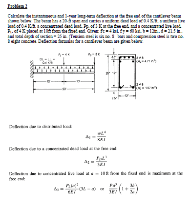


Solved For All The Following Problems Perform All The Ne Chegg Com


Http Kaizenha Com Cdn Files Strength Manual solution 8th eddition Ch11 12 beams shafts design deflection Pdf


Simple Stresses
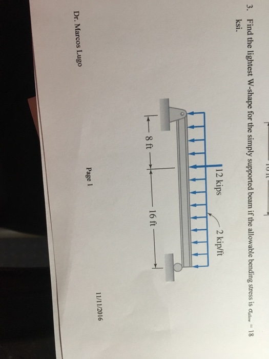


Solved Find The Lightest W Shape For The Simply Supported Chegg Com


Strength Of Materials


Uotechnology Edu Iq Dep Bme English Pages Lectures Resestance Strength of materials solutions Ferdinand l singer andrew pytel Pdf


Http Faculty Arch Tamu Edu Anichols Courses Elements Architectural Structures Notes 614 Files Package Fnyrkto 1 414 Compressed Pdf
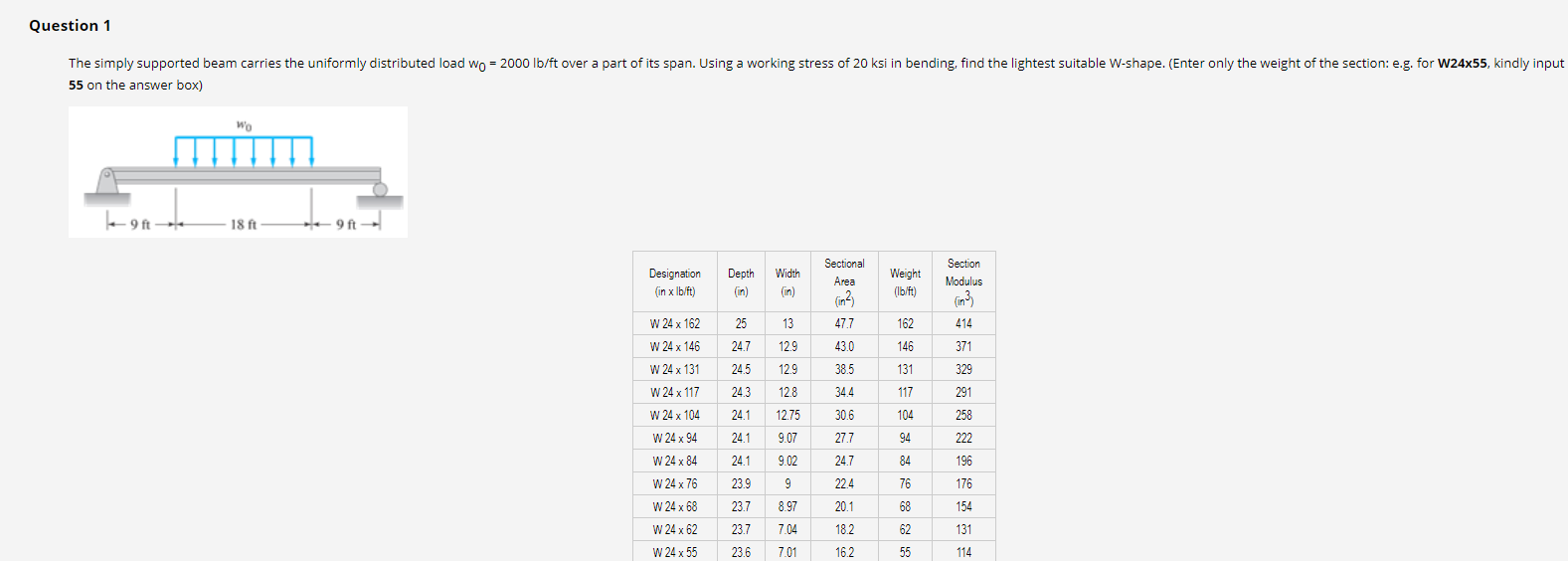


Solved Question 1 The Simply Supported Beam Carries The U Chegg Com


Www Aisc Org Globalassets Aisc Manual V15 1 Companion V15 1 Vol 1 Design Examples Pdf


Http Kaizenha Com Cdn Files Strength Manual solution 8th eddition Ch11 12 beams shafts design deflection Pdf


Timber Design Bending Beam Structure
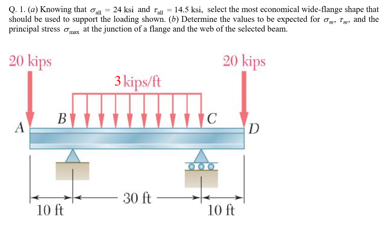


Solved Q 1 A Knowing That All 24 Ksi And Tail 14 Chegg Com


Http Faculty Arch Tamu Edu Anichols Courses Elements Architectural Structures Notes 614 Files Package Fnyrkto 1 414 Compressed Pdf


Sites Lafayette Edu Kurtzs Files 18 11 Exam 3 Past Exams With Solutions Pdf


Sites Lafayette Edu Kurtzs Files 18 11 Exam 3 Past Exams With Solutions Pdf


Mechanics Of Materials Pages 151 0 Flip Pdf Download Fliphtml5
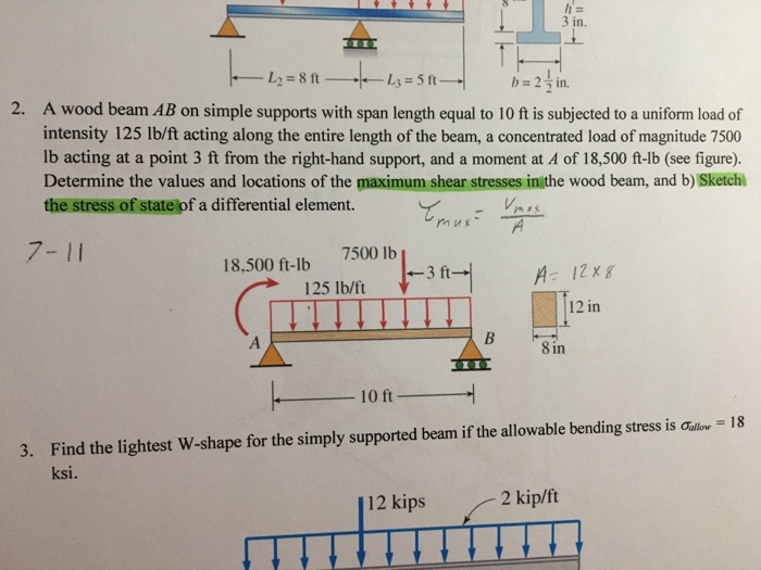


Solved A Wood Beam Ab On Simple Supports With Span Length Chegg Com


Sites Lafayette Edu Kurtzs Files 18 11 Exam 3 Past Exams With Solutions Pdf


Aisc Parte 2 By William Gamboa Issuu


Mechanics Of Materials Chapter 5 Stresses In Beams
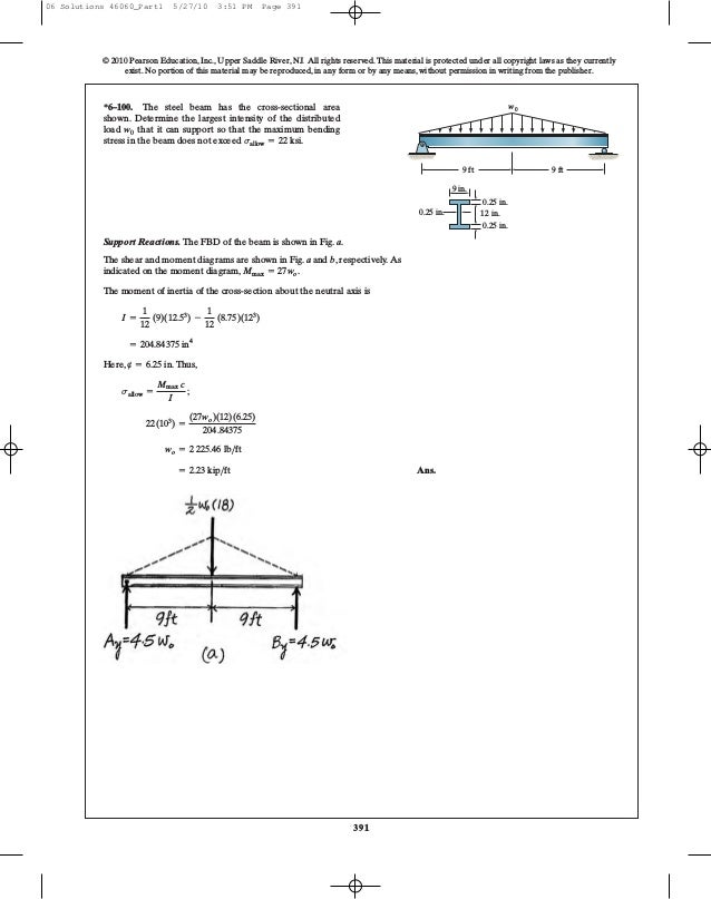


Ch06 07 Pure Bending Amp Transverse Shear


Sites Lafayette Edu Kurtzs Files 18 11 Exam 3 Past Exams With Solutions Pdf


Elastic Bending Of Beams Springerlink


Elastic Bending Of Beams Springerlink


Uotechnology Edu Iq Dep Bme English Pages Lectures Resestance Strength of materials solutions Ferdinand l singer andrew pytel Pdf
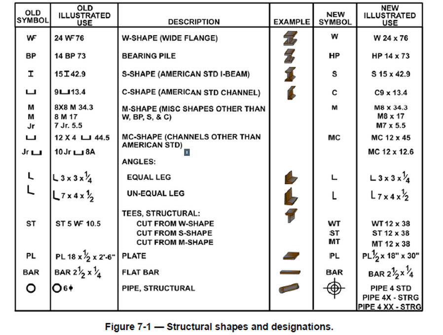


Structural Steel Drawings Computer Aided Drafting Design


Http Web Ncyu Edu Tw Lanjc Lesson C3 Class Chap05 A Pdf


Problem 3 Design Of Steel Beam For Bending With Varying Unbraced Lengths Select The Lightest 92 Homeworklib


Uotechnology Edu Iq Dep Bme English Pages Lectures Resestance Strength of materials solutions Ferdinand l singer andrew pytel Pdf


Taller De Esfuerzo En Vigas Bending Beam Structure
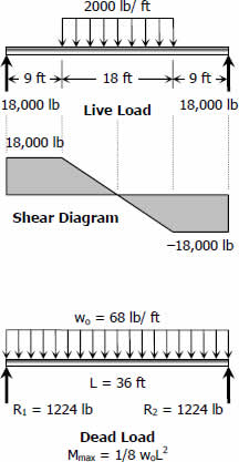


Solution To Problem 533 Economic Sections Strength Of Materials Review At Mathalino


Http Kaizenha Com Cdn Files Strength Manual solution 8th eddition Ch11 12 beams shafts design deflection Pdf
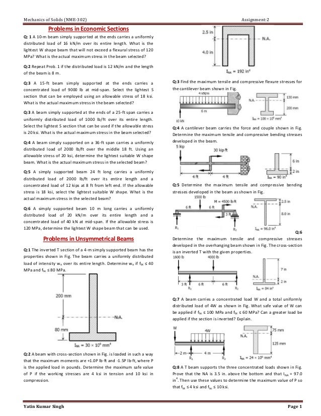


Assignment 2
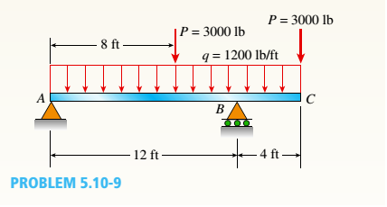


A Simple Beam With An Overhang Supports A Uniform Load Of Intensity Q 10 Lb Ft And A Concentrated P 3000 Lb Load At 8 Ft To The Right Of A
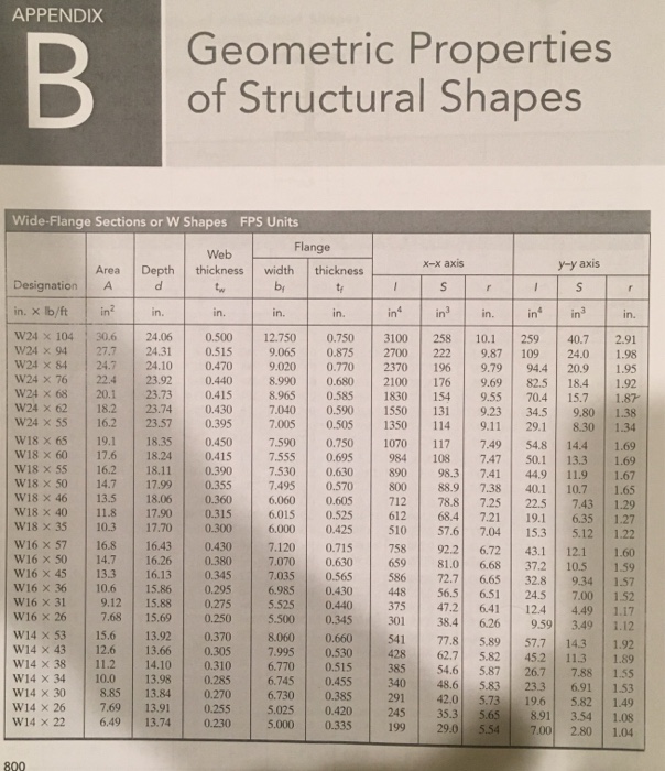


Solved Find The Lightest W Shape For The Simply Supported Chegg Com


Http Www Mongroupsydney1 Com 1 Pdf
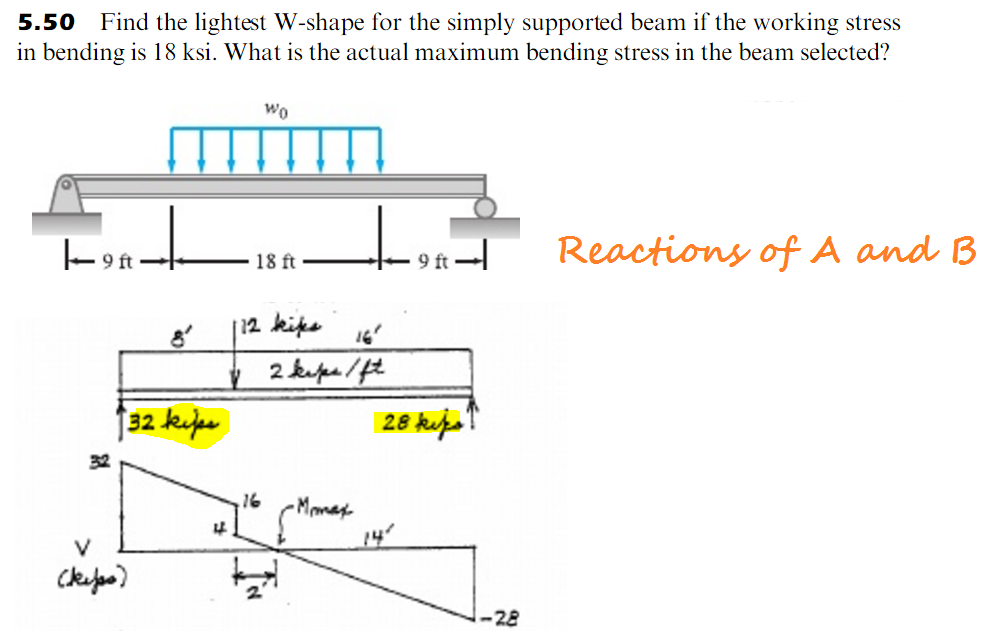


5 50 Find The Lightest W Shape For The Simply Supp Chegg Com
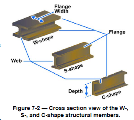


Structural Steel Drawings Computer Aided Drafting Design


Mechanics Of Materials Pages 151 0 Flip Pdf Download Fliphtml5


Resistencia De Materiales 4ta Edicion Andrew Pytel Ferdinand Singer Sol By Pavel Jose Camero Zavaleta Issuu


Http Www Mongroupsydney1 Com 1 Pdf


Solved Find The Lightest W Shape For The Simply Supported Chegg Com


End Of Chapter Practice Problems Mcgraw Hill Education Access Engineering


Steel Design Examples


Structural Elements For Architects And Builders Jonathan Ochshorn By Jeroen Van Den Bovenkamp Issuu


Solved Find The Lightest S Shape For The Beam Shown If The Working Stress 1 Answer Transtutors


Www Aisc Org Globalassets Aisc Manual V15 1 Companion V15 1 Vol 1 Design Examples Pdf


Faculty Arch Tamu Edu Media Cms Page Media 4198 Ns22 1cncrtdesign 3 Pdf


Http Web Ncyu Edu Tw Lanjc Lesson C3 Class Chap05 A Pdf


Sites Lafayette Edu Kurtzs Files 18 11 Exam 3 Past Exams With Solutions Pdf


D Select The Lightest Weight Steel Wide Flange Overhanging Beam From Appendix B That Will Safely Support Homeworklib


Http Www Lsiskl Lt Naudinga Item Download 47 097ad286b8043c3be09f925d


コメント
コメントを投稿